Why Choose an M6.5 Scanning Lens for Laser Marking?
Choosing a scanning lens can directly affect marking clarity, speed, and production consistency. The M6.5 Scanning Lens is designed for applications requiring a balanced working distance and controlled laser focus. In practical use, this balance helps operators mark logos, serial numbers, barcodes, and fine patterns with cleaner edges. A stable focal plane also reduces visible distortion across the marking field.
Small details matter. During setup, technicians should check the lens coating, compatible wavelength, scan field, and actual working distance. A lens may perform well on anodized aluminum but require different settings on stainless steel or coated plastics. Galvo calibration, beam alignment, and software correction remain equally important. The lens cannot fix every system problem.
Real production experience also shows that speed claims need careful evaluation. Faster scanning may increase output, but excessive speed can reduce contrast or create uneven lines. The M6.5 Scanning Lens should be selected according to the laser source, beam quality, marking size, and material response. Verify the manufacturer’s specifications, then test representative samples before full-scale installation. That step is easy to overlook.
A reliable choice is rarely based on one number. It depends on the complete optical system and the operator’s process knowledge. Even experienced users may need to refine focus and power settings. That is normal. With proper testing and maintenance, an M6.5 Scanning Lens can support precise, repeatable laser marking across demanding industrial workflows.
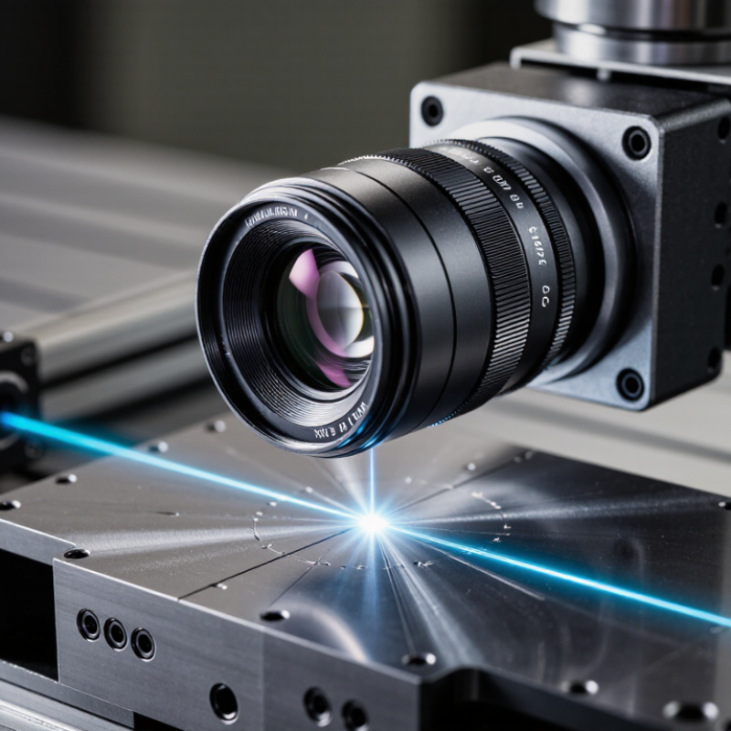
Why Choose an M6.5 Scanning Lens for Laser Marking?
An M6.5 scanning lens is not a universal ISO classification. In practice, M6.5 usually identifies a lens model, optical magnification, or focal specification defined by a supplier. That label alone is insufficient. Engineers should verify working distance, scan field, wavelength range, spot size, distortion, and compatible scan-head aperture. ISO 11145 defines laser terminology, but it does not standardize the commercial term “M6.5.” This distinction matters during equipment selection.
For laser marking, the lens focuses the beam across a two-dimensional field. A suitable M6.5 design can support fine characters, compact QR codes, and controlled energy density on metal or coated surfaces. However, a wider field normally increases spot size and may reduce detail. There is no perfect lens.
Grand View Research reported that the global laser marking market reached about USD 3.07 billion in 2023, with projected growth of 8.7% annually from 2024 to 2030. That expansion increases demand for stable, repeatable optical performance. In practical testing, technicians should mark a calibration grid, inspect edge distortion, and measure line width at the field corners. I have found that the center often looks excellent, while the edges reveal the real limitation. Lens performance also depends on beam quality, pulse settings, surface reflectivity, and thermal focus drift. A datasheet cannot replace a material test.
| Data Dimension | Typical Reference Data | Why It Matters in Laser Marking |
|---|---|---|
| Lens Type | F-theta scanning lens | Designed to keep the focused spot close to a linear relationship with the galvo mirror angle across the marking field. |
| Meaning of “M6.5” | A model or optical-series designation; it is not a universal international specification. | The exact focal length, aperture, scan field, and wavelength must be confirmed from the lens drawing or technical datasheet. |
| Common Laser Wavelength | Often configured for 1,064 nm fiber or solid-state laser systems; other versions may support 355 nm, 532 nm, or 10.6 µm. | Optical coatings and lens materials must match the laser wavelength to reduce reflection losses and prevent coating damage. |
| Typical Scan-Field Range | Approximately 50 × 50 mm to 110 × 110 mm for many compact marking configurations. | A smaller field generally supports a smaller focused spot, while a larger field covers more parts in one setup. |
| Effective Focal Length | Common marking-lens values are approximately 100–170 mm, depending on the required scan field and beam diameter. | Focal length influences the working distance, spot size, scan area, and compatibility with the beam expander. |
| Working Distance | Typically about 100–200 mm from the reference lens surface to the marking plane, depending on lens design. | Correct working distance is required to place the smallest focused spot on the workpiece surface. |
| Focused Spot Size | Commonly around 30–80 µm in a properly matched 1,064 nm marking system; the actual value depends on beam quality, beam diameter, and focal length. | A smaller spot can improve line width, edge definition, text readability, and marking resolution. |
| Optical Aperture | Often selected in the approximate range of 10–20 mm for compact galvo marking systems. | The aperture must accommodate the expanded laser beam without significant clipping or power loss. |
| Field Distortion | F-theta correction is used to reduce nonlinear positioning errors across the scan field. | Lower distortion helps maintain accurate dimensions for logos, barcodes, serial numbers, and geometric patterns. |
| Marking Speed Compatibility | Suitable speed depends on the galvo scanner, laser power, material, pulse duration, and marking strategy. | The lens alone does not determine the maximum marking speed; the complete optical and motion system must be matched. |
| Material Compatibility | Optical glass or infrared-transmitting materials are selected according to the operating wavelength. | Using a lens outside its specified wavelength range can reduce transmission and may cause thermal or coating damage. |
| Best-Suited Applications | Fine text, QR codes, barcodes, serial numbers, graphics, shallow engraving, and small-to-medium components. | The compact scan field and potentially small spot size can provide a useful balance between detail and coverage. |
| Main Selection Advantage | Balanced coverage, focusing performance, and integration with compact galvo laser markers. | An appropriately selected M6.5 lens can improve marking consistency without requiring a large optical assembly. |
| Key Verification Items | Wavelength, scan field, focal length, working distance, clear aperture, coating range, distortion, and connector or mount dimensions. | Checking these specifications prevents incompatibility with the laser source, beam expander, galvo scanner, and marking software. |
Note: “M6.5” is not a globally standardized lens specification. Actual performance values vary by optical design and should be confirmed against the specific technical datasheet before selection.